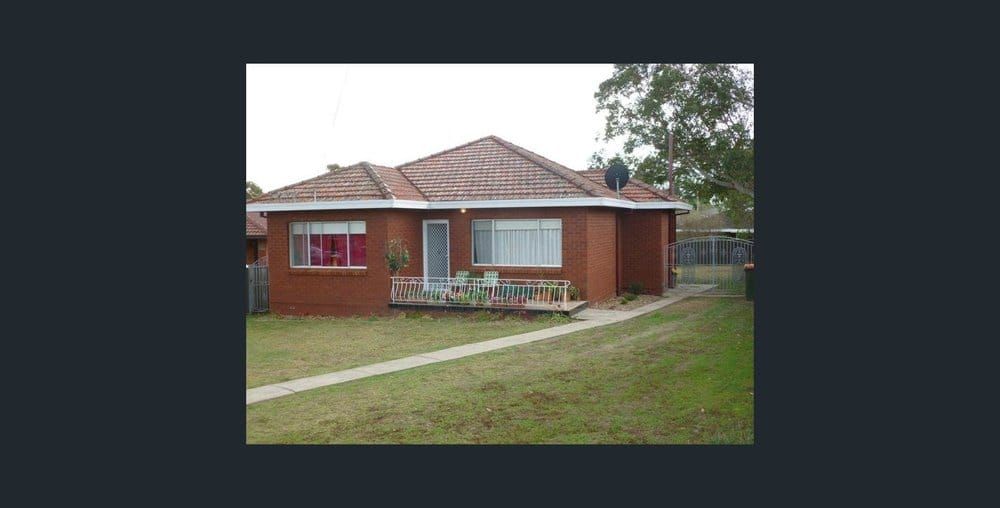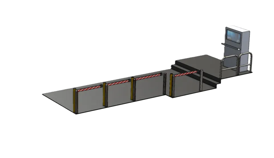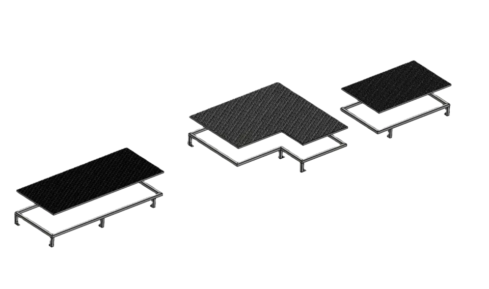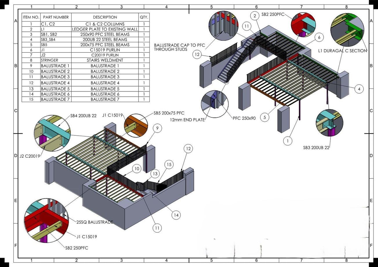
Location: 6 O’Connell St, Sydney
Sector: Commercial / Structural
Project Type: Mezzanine design and fabrication documentation
Role Focus: 3D structural modelling, technical drafting and fabrication support
This project involved supporting the engineering development of a commercial mezzanine level within an existing building at 6 O’Connell Street, Sydney.
The work required the proposed mezzanine structure to be developed around an established building environment while considering structural interfaces, available space, fabrication requirements and practical installation.
My contribution focused on 3D structural modelling, technical drafting and the development of fabrication-oriented engineering documentation.
The project strengthened my experience in converting structural engineering requirements into coordinated technical information capable of supporting manufacture and site implementation.
Project Context
Adding a mezzanine level to an existing commercial building creates a different engineering challenge from designing a new structure on an unrestricted site.
The proposed structure needs to work within an existing physical environment.
This means the design needs to consider:
- Existing building geometry
- Available structural interfaces
- Floor levels
- Access
- Supporting members
- Connection locations
- Fabrication
- Installation
- Existing services and surrounding features
- Commercial-space requirements
The mezzanine therefore needed to be considered as part of the existing building rather than as an independent structure.
Existing-Building Integration
A major part of the design challenge was understanding how the new structure would interact with what was already in place.
Existing buildings create fixed boundaries.
Columns, walls, floors, ceilings, access routes and services can all restrict where new structural members can be positioned.
The engineering process therefore began from the existing condition.
The key relationship was:
Existing Building + New Mezzanine + Structural Interfaces + Access + Installation
rather than simply designing the ideal mezzanine in isolation.
This is a form of brownfield engineering within the commercial-building environment.
3D Structural Modelling
Three-dimensional modelling was used to develop and coordinate the proposed mezzanine structure.
The 3D environment provided a clearer understanding of how structural members related to the surrounding building.
This supported review of:
- Member position
- Structural geometry
- Levels
- Connection locations
- Clearances
- Supporting elements
- Access
- Potential interferences
Using 3D modelling was particularly valuable because mezzanine structures include several intersecting elements that can be difficult to fully understand from isolated 2D views.
The model therefore became both a design-development and coordination tool.
Structural Member Coordination
The mezzanine required structural members to be arranged so that loads could be transferred through the proposed supporting system while remaining compatible with the building layout.
My role focused on representing the structural engineering requirements accurately within the model and technical drawings.
The design information needed to coordinate elements such as:
- Beams
- Columns or supporting members
- Floor framing
- Edge members
- Connections
- Supporting interfaces
- Access openings
Structural analysis, load verification and formal certification remained with the responsible structural engineer.
Load-Bearing Requirements
The existing project description identifies the mezzanine as a high-load commercial structure.
This meant that the structural arrangement needed to reflect the design loads specified by the engineering team.
From a documentation perspective, this required accurate representation of:
- Member sizes
- Support positions
- Connection interfaces
- Structural relationships
- Floor-support arrangement
My role was not to independently certify the structural capacity.
Instead, my contribution was to ensure that the approved engineering requirements were translated consistently into the design and fabrication documentation.
Fabrication-Oriented Design
A major strength of this project was the relationship between structural modelling and fabrication.
The mezzanine could not remain a conceptual structure.
Its individual components ultimately needed to be manufactured.
Technical information therefore needed to consider how structural elements would be:
- Cut
- Drilled
- Welded
- Connected
- Transported
- Assembled
- Installed
This required a practical engineering mindset.
A model can appear correct digitally but still create unnecessary problems if fabrication and assembly have not been considered.
The project reinforced the importance of developing engineering information around real manufacturing methods.
Structural Connections
Connections are particularly important in fabricated structural systems.
Individual members only become a functioning structure when they are connected correctly.
Documentation therefore needed to clearly represent relevant connection requirements and interfaces.
Depending on the engineering details provided, this could involve representation of:
- Plates
- Brackets
- Bolt locations
- Welded components
- Beam interfaces
- Supporting members
The project strengthened my understanding that many structural fabrication issues occur at interfaces rather than within the main members themselves.
This same principle appears repeatedly throughout engineering:
the connection between components often deserves as much attention as the components themselves.
Design for Fabrication
The structure needed to be capable of being manufactured efficiently.
This meant considering practical fabrication constraints during modelling and detailing.
Relevant considerations included:
- Standard structural sections
- Material availability
- Cutting requirements
- Welding access
- Hole positioning
- Connection detail
- Component repeatability
- Workshop handling
Simplifying unnecessary complexity can improve both fabrication efficiency and installation reliability.
This is directly aligned with the design-for-manufacture thinking that has been important throughout my mechanical and product-development career.
Constructability
The project also required consideration of how the mezzanine could actually be installed inside the existing building.
This is particularly important because commercial buildings can impose significant access constraints.
The design therefore needed to remain conscious of questions such as:
- Can the fabricated members enter the building?
- Can they be manoeuvred into position?
- Is sufficient installation access available?
- Does the sequence of assembly matter?
- Can connections be reached once members are positioned?
- Will installation interfere with existing building features?
This reinforced an important project principle:
A structure is not fully designed until there is a practical way to build it.
Installation Sequencing
Mezzanine construction naturally involves dependencies.
A typical structural sequence may involve:
Supports → Primary Members → Secondary Framing → Connections → Floor System → Completion
The exact sequence remained the responsibility of the construction team, but engineering documentation needed to be clear enough to support that planning.
This provided another example of how detailed technical work connects with wider project-delivery considerations.
Spatial Coordination
The existing-building environment meant that structural components needed to be coordinated with surrounding physical features.
Three-dimensional modelling helped reduce the risk of interference between the proposed structure and existing building elements.
Spatial coordination can prevent downstream issues such as:
- Structural clashes
- Access conflicts
- Connection difficulties
- Installation problems
- Site modification
- Rework
This reinforced the value of solving foreseeable issues during design rather than transferring them to site.
Technical and Fabrication Drawings
Detailed drawings translated the 3D structural model into information usable by fabrication and project teams.
Documentation needed to clearly communicate:
- Overall structural arrangement
- Member geometry
- Dimensions
- Connections
- Component relationships
- Fabrication information
- Assembly references
- Drawing revisions
These drawings provided the link between the structural engineering requirement and physical fabrication.
Drawing and Revision Control
As with most engineering projects, design information can evolve during development.
Any change needed to remain coordinated between:
- 3D models
- General arrangement drawings
- Detail drawings
- Fabrication information
- Related components
This required disciplined revision management.
The project strengthened my experience in maintaining consistency between interconnected technical documents.
Engineering-to-Fabrication Interface
One of the most valuable aspects of this project was understanding the information chain between engineering and the workshop.
The process can be represented as:
Structural Requirement → 3D Model → Detail Drawing → Fabrication → Installation
An error or ambiguity at the modelling stage can ultimately become a fabrication or site problem.
The project therefore reinforced the importance of accurate engineering communication.
Engineering-to-Site Interface
The project also demonstrated how structural documentation supports site implementation.
Fabricated steel needs to arrive on site with enough information and accuracy to be assembled into the intended structure.
This means engineering documentation needs to support not only fabrication but also:
- Member identification
- Positioning
- Connection
- Assembly
- Installation verification
The drawings therefore functioned as project-delivery tools, not simply design outputs.
Stakeholder Coordination
Commercial structural projects involve several different stakeholders.
These may include:
- Structural engineers
- Building designers
- Fabricators
- Site teams
- Project managers
- Client representatives
Each group uses the engineering information differently.
My contribution focused on maintaining clear technical documentation capable of supporting communication between these functions.
This strengthened an important capability that later became increasingly central to my career:
using engineering information to align multiple stakeholders around the same physical outcome.
Project Deliverables
My contribution included work associated with:
- 3D structural modelling
- Mezzanine general arrangement development
- Structural member coordination
- Existing-building integration
- Structural-detail drafting
- Fabrication-oriented drawings
- Connection and interface documentation
- Spatial coordination
- Constructability considerations
- Design revisions
- Technical-documentation control
- Information supporting fabrication and site implementation
Structural calculations, building certification and final engineering approval remained with the appropriately qualified structural and project professionals.
Project Outcome
The project produced coordinated 3D structural and fabrication documentation supporting development of the proposed commercial mezzanine.
Its professional value for me extended beyond structural drafting.
It strengthened my understanding of the complete engineering information chain:
Requirement → Engineering → Model → Fabrication → Installation
The project demonstrated that successful engineering requires technical information to remain connected to how the final structure will actually be manufactured and built.
Capabilities Demonstrated
Structural Design Support
Translating structural engineering requirements into coordinated models and technical drawings.
3D Structural Modelling
Using three-dimensional engineering information to understand geometry, interfaces and spatial relationships.
Existing-Building Integration
Developing a new structure around established building constraints.
Fabrication Engineering
Producing technical information suitable for structural-steel manufacture.
Design for Manufacture
Considering material, fabrication and assembly requirements during design development.
Constructability
Understanding how the final structure could be practically delivered and installed.
Structural Interface Coordination
Managing the relationship between members, connections, supports and surrounding building elements.
Spatial Coordination
Identifying physical conflicts before fabrication and site installation.
Revision Control
Maintaining consistency between models and interconnected drawings as the design developed.
Engineering-to-Fabrication Translation
Connecting engineering intent with the information required by manufacturing teams.
Engineering-to-Site Coordination
Developing documentation capable of supporting construction and installation activities.
Career Development
The 6 O’Connell Street mezzanine project is another useful example of how my career developed beyond simply producing CAD drawings.
The visible outputs were models and fabrication drawings, but the real engineering questions were broader:
What already exists?
Where can the structure fit?
How do new members interface with the building?
Can the parts be manufactured?
How will they be transported and installed?
Are the connections accessible?
What information does the fabricator require?
What information does the site team require?
Those are project-delivery questions as much as drafting questions.
The project therefore strengthened another part of the progression in my career:
Technical Drawing → Engineering Coordination → Fabrication → Constructability → Project Delivery
As my later responsibilities expanded into manufacturing engineering, operations excellence and project management, the scale of the work changed, but the same fundamental principle remained:
engineering information only creates value when it can be translated successfully into a physical outcome.