Client: RoboHelix Manufacturing
Industry: Automotive & Electronics
Project Period: 2019
Role: Mechanical Design and Manufacturing Drafting
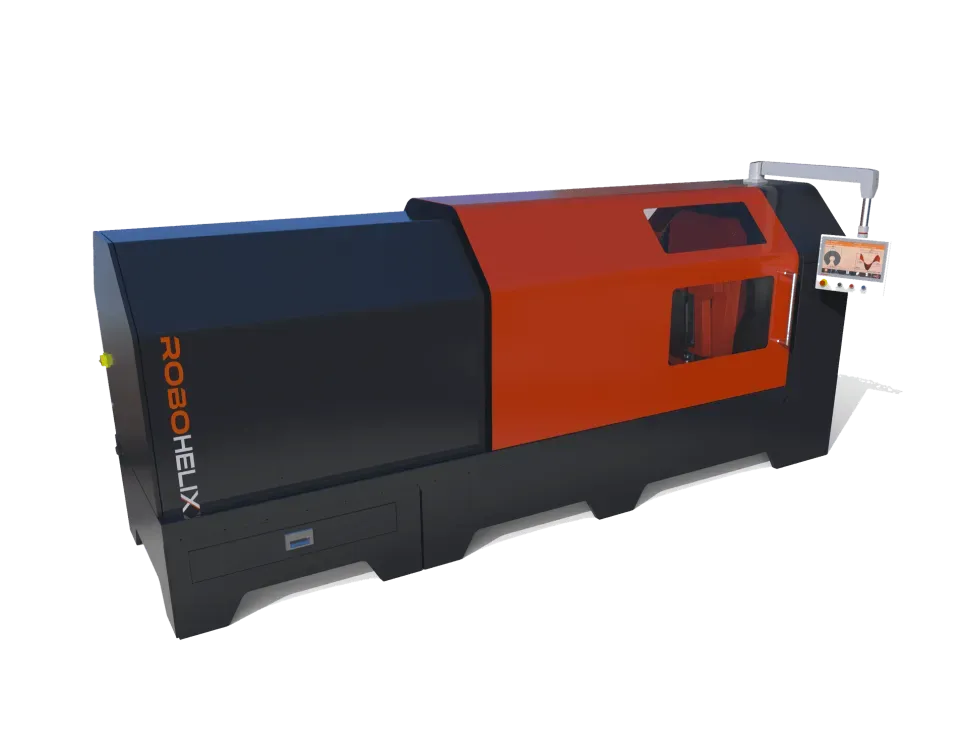
This project involved supporting the development of a precision helical-coiling machine designed to manufacture fine-wire coils for automotive and electronics applications.
The engineering challenge required translating developing machine concepts into accurate 3D models and manufacturing documentation that could be understood and used by fabricators, machinists and assembly personnel.
My contribution focused on parametric SolidWorks modelling, detailed component and assembly documentation, dimensional definition, manufacturing considerations and the accurate representation of complex mechanical geometry.
The project strengthened an area that has remained fundamental throughout my career:
connecting engineering design with the information required to manufacture and assemble a real machine.
Project Context
Precision coiling equipment operates in an environment where relatively small dimensional differences can significantly influence machine performance and final product quality.
The mechanical design therefore required a high level of accuracy and disciplined technical documentation.
The machine included components and assemblies that needed to work together consistently while supporting the controlled formation of fine wire into helical geometries.
The engineering documentation needed to communicate:
- Component geometry
- Assembly relationships
- Critical dimensions
- Tolerances
- Materials
- Surface finishes
- Machining requirements
- Welding requirements
- Manufacturing notes
The challenge was not simply to represent the machine visually.
The CAD models and drawings needed to provide sufficient engineering definition for components to be manufactured and assembled correctly.
From Engineering Concept to Manufacturable Definition
The project involved working alongside the developing engineering concept rather than receiving a completely fixed design.
As the machine evolved, the corresponding CAD models and manufacturing information also needed to evolve.
This required an iterative engineering workflow:
Engineering Requirement → CAD Development → Design Review → Revision → Manufacturing Documentation
Changes to one component could influence surrounding parts, interfaces or assemblies.
Parametric modelling was therefore particularly valuable because design relationships could be managed more systematically as the machine developed.
This provided useful experience in design environments where engineering information changes progressively rather than arriving as a finished specification.
Parametric SolidWorks Modelling
SolidWorks was used to develop detailed parametric 3D models of machine components and assemblies.
Parametric modelling allowed dimensions and relationships to be controlled through defined features rather than treating each component as static geometry.
This supported:
- Design iteration
- Dimensional updates
- Component relationships
- Assembly development
- Design review
- Drawing generation
- Manufacturing communication
For a precision machine, maintaining consistency between the model and the associated manufacturing drawings was particularly important.
The CAD model became part of the engineering definition of the machine rather than simply a visual aid.
Precision Mechanical Geometry
One of the more technically demanding aspects of the work involved representing the geometry associated with the helical-coiling mechanism.
Helical and curved machine elements can introduce challenges because their geometry is three-dimensional and often influenced by several related parameters.
The design information therefore needed to accurately represent relationships such as:
- Diameter
- Pitch
- Curvature
- Position
- Orientation
- Component interfaces
Careful geometric development was required so that the design intent could be communicated accurately through both the 3D model and manufacturing drawings.
This project strengthened my understanding of how mathematical and geometric relationships translate into actual machine components.
Manufacturing Drawings
A substantial part of the work involved developing manufacturing drawings from the 3D design.
The drawings included information required for fabrication and machining, such as:
- Multiple component views
- Dimensions
- Dimensional tolerances
- Material requirements
- Surface-finish information
- Machining notes
- Welding information
- Assembly references
- Technical notes
The original project documentation referenced ISO 128 drawing conventions as part of the documentation approach.
The objective was to create information that could be interpreted consistently across the manufacturing supply chain.
Tolerance Thinking
Precision machinery requires more than accurate nominal dimensions.
How much a dimension is allowed to vary can be equally important.
Tolerance therefore formed an important part of the manufacturing documentation.
The project strengthened my understanding that tolerances should relate to functional requirements rather than simply being made unnecessarily tight.
Excessively tight tolerances can increase:
- Machining time
- Manufacturing cost
- Inspection requirements
- Supplier difficulty
- Rejection risk
while tolerances that are too loose can compromise machine performance.
The engineering challenge is to define the level of precision actually required by the function.
That relationship between function, tolerance and manufacturing cost has remained important throughout my later product-development and manufacturing work.
Design for Manufacture
Manufacturability was considered as the machine design developed.
A CAD model can be geometrically correct but still create unnecessary difficulty for the people who need to manufacture it.
The design process therefore considered practical issues including:
- Machining access
- Standard material forms
- Welding access
- Component complexity
- Surface requirements
- Assembly
- Inspection
- Supplier capability
Where possible, engineering information needed to support straightforward manufacturing rather than introduce avoidable complexity.
This reinforced one of the key principles that later influenced my product-development work:
Design decisions need to be made with an understanding of how the component will actually be produced.
Supplier Communication
Manufacturing drawings become the primary technical communication between engineering and the supplier.
This becomes even more important where components may be produced by different suppliers.
A drawing needs to provide enough information so that the component does not depend on undocumented assumptions.
The documentation therefore needed to communicate the design intent clearly and consistently.
This project gave me valuable experience in understanding engineering drawings as contractual and manufacturing information rather than simply internal design records.
Assembly Coordination
Individual components also needed to function correctly when brought together into the machine assembly.
The 3D environment helped evaluate component relationships and identify potential issues before physical assembly.
This included reviewing:
- Fit
- Alignment
- Interference
- Fastener access
- Assembly sequence
- Component orientation
- Service access
This assembly-level perspective strengthened my understanding of the relationship between individual part design and complete machine performance.
Design Changes and Revision Management
Because the machine was evolving, design changes needed to be incorporated without losing control of the technical information.
A change to one component could require updates to:
- The part model
- Related components
- Assembly models
- Manufacturing drawings
- Dimensions
- Notes
- Revision status
Managing these relationships is an important part of mechanical engineering project work.
This experience later became directly relevant to my product-development responsibilities, where engineering changes needed to be coordinated across drawings, tooling, quality and manufacturing.
Engineering Quality Assurance
Precision manufacturing documentation requires disciplined checking.
The original project used a staged drawing-review process involving self-checking, peer review and engineering sign-off before drawings were released.
This reinforced the importance of separating:
Creation → Checking → Approval
rather than assuming that the person who produced the information should also be the only person verifying it.
This principle has remained valuable throughout my later engineering and project-delivery work.
Manufacturing and Engineering Interface
One of the most valuable aspects of this project was working at the interface between engineering intent and manufacturing reality.
Engineering defines what the machine must do.
Manufacturing determines how the physical components can be produced.
Technical documentation connects the two.
The workflow can be represented as:
Engineering Concept → 3D Model → Manufacturing Drawing → Supplier → Component → Assembly → Machine
An error or ambiguity at any point in that information chain can affect the final equipment.
The project therefore strengthened my appreciation for the importance of accurate and controlled engineering information throughout the product-development lifecycle.
Project Deliverables
My contribution included work associated with:
- Parametric SolidWorks modelling
- Mechanical component development
- Assembly modelling
- Precision geometry development
- Helical and curved geometry representation
- Detailed manufacturing drawings
- Dimensional definition
- Tolerance specification
- Material information
- Surface-finish requirements
- Machining notes
- Welding information
- Assembly documentation
- Design revisions
- Manufacturing-documentation control
- Engineering review support
Project Outcome
The engineering work produced a detailed manufacturing-documentation package supporting fabrication and assembly of the RoboHelix machine.
The original project record states that the equipment subsequently progressed into operation producing helical coils for its intended manufacturing applications.
From my career perspective, the most important outcome was the experience gained in taking developing engineering ideas and converting them into precise manufacturing information.
This work required a combination of:
Mechanical Understanding + CAD Capability + Tolerance Knowledge + Manufacturing Awareness + Documentation Discipline
It strengthened the engineering foundation that later supported my progression into product development, manufacturing improvement and engineering project delivery.
Capabilities Demonstrated
Precision Mechanical Design
Developing and documenting machine components where geometry and dimensional accuracy were important to functional performance.
SolidWorks
Creating parametric parts and assemblies capable of supporting iterative engineering development.
Manufacturing Engineering
Understanding the relationship between engineering definition and fabrication or machining requirements.
Engineering Drawings
Producing detailed technical documentation suitable for component manufacture and machine assembly.
Geometric Problem-Solving
Representing complex helical and curved geometries within practical engineering documentation.
Tolerance Management
Considering how dimensional variation influences function, quality and manufacturing cost.
Design for Manufacture
Considering machining, welding, material selection and production practicality during engineering development.
Assembly Coordination
Evaluating component interfaces, clearances and assembly relationships within the complete machine.
Design Change Management
Updating interconnected models and drawings as the engineering design evolved.
Quality Assurance
Working within a structured drawing-review and engineering-sign-off process.
Supplier Communication
Using technical documentation to communicate engineering intent clearly to manufacturing suppliers.
Engineering-to-Manufacturing Translation
Converting developing machine concepts into controlled information capable of supporting physical production.
Career Development
This project represents an important point in my professional development because it moved my work deeper into precision machine engineering and manufacturing documentation.
The task was no longer simply:
“Draw this component.”
The real responsibility was understanding:
What function does the component perform?
How does it interface with surrounding parts?
Which dimensions are critical?
What tolerance is required?
How will it be manufactured?
How will it be inspected?
How will it be assembled?
What happens elsewhere in the machine if the design changes?
That thinking represents a significant transition from drafting toward engineering design.
It also established the foundation for much of my later work.
The progression became:
Component → Assembly → Machine → Manufacturing Process → Production System → Project Delivery
Today, when I work on manufacturing or operations projects, I still draw on the discipline developed through projects such as RoboHelix.
My responsibilities have broadened into scope, stakeholders, contractors, cost, implementation, commissioning and handover, but the technical foundation remains important.
It allows me to understand how project-level decisions eventually become physical engineering outcomes on the factory floor.